
+86-13205638142

Views: 0 Author: Site Editor Publish Time: 2026-08-07 Origin: Site


Uneven wear on crushing equipment accelerates maintenance cycles significantly. It reduces your yield quality and artificially inflates your operational costs over time. Plant operators face constant production disruptions because of this issue. We must treat one-sided wear carefully. It is not just a frustrating mechanical nuisance. It acts as a critical indicator of suboptimal feed distribution. It might also signal an incorrect chamber configuration or mismatched metallurgy inside your crushing equipment.
Plant managers need reliable strategies to overcome these challenges. Reliability engineers must diagnose these issues quickly to prevent further equipment degradation. We provide a comprehensive diagnostic framework below. You will learn to identify specific root causes effectively. You will also discover how to evaluate permanent hardware upgrades. We guide you through essential operational solutions to stabilize your production flow.
Uneven wear is most frequently caused by feed segregation (fines separated from coarse material) prior to entering the crushing chamber.
Continuing to operate with severely asymmetrical wear drastically increases the risk of component failure (e.g., main shaft stress, bearing damage).
Correcting the issue requires a dual approach: optimizing the feed arrangement and upgrading to application-specific crusher liners tailored to the site's rock hardness and abrasiveness.
Selecting the right replacement components—including specialized Jaw Crusher Plates and Side Liners—demands evaluating alloy composition and chamber profiles, not just price.
Localized wear forces premature replacement cycles across your entire crushing circuit. You end up discarding otherwise usable manganese steel. This waste occurs because one side of the component wears down to the backing material early. The other side might still retain plenty of functional thickness. This imbalance drastically increases your planned downtime. Maintenance teams spend excessive hours changing out parts prematurely. You burn through your replacement inventory much faster than necessary.
Uneven wear directly correlates with an inconsistent Closed Side Setting (CSS). Your equipment struggles to maintain a uniform crushing gap. This inconsistency leads to poor particle shape across your aggregate output. You will notice increased flakiness and elongation in your final product. Your screening circuit will eventually reject more out-of-spec aggregate. This rejection loop wastes energy and lowers your total sellable yield.
Asymmetrical wear does more than ruin product shape. It transfers severe uneven pressure directly into the core mechanical components. You place unnatural stress on the eccentric bearings. The pitman and main frame absorb dangerous lateral forces. Industry evidence shows a clear link between sustained uneven crushing forces and catastrophic mechanical failures. Bearings overheat, and main shafts can suffer micro-fractures under this continuous stress.
You need clear metrics to measure improvement in your crushing circuit.
Achieve uniform wear across the entire crushing chamber.
Utilize at least 60-70% of the component mass before replacement becomes necessary.
Stabilize your daily material throughput.
Protect the machine from damaging lateral vibrations.
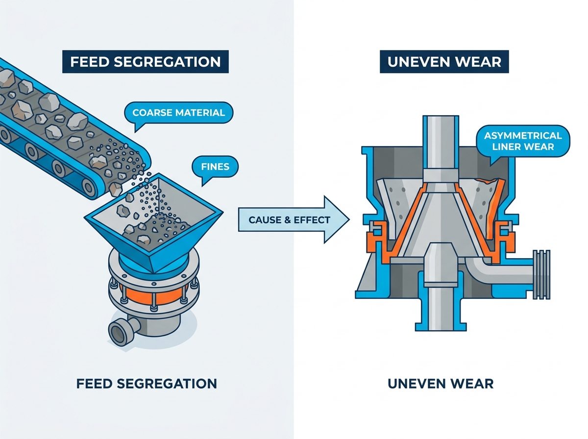
Feed segregation remains a leading cause of localized damage. Conveyor discharge patterns frequently push large rocks to one side of the feed box. Fines naturally migrate to the opposite side. This separation causes highly localized abrasion. The coarse material creates intense impact zones. The fines side experiences high friction but lacks the impact needed for proper work-hardening. This imbalance destroys components rapidly.
Operators must maintain a full, centralized feed block. We call this choke feeding. Lack of proper choke feeding prevents beneficial rock-on-rock crushing. The incoming material strikes the bare metal directly instead. The machinery must absorb the full impact of every rock. This operational failure accelerates localized deterioration rapidly.
Structural issues often contribute to poor wear patterns. You might have uneven feed chutes directing material off-center. Misaligned hoppers dump rocks strictly onto one wall of the chamber. Incorrect structural leveling creates natural gravity biases. You must inspect your entire upstream conveying setup. Small alignment errors cascade into massive mechanical imbalances inside the crushing chamber.
Using standard off-the-shelf OEM profiles for specialized applications introduces major risks. These generic profiles force unnatural contact patterns onto specific zones of your equipment. They do not account for unique feed characteristics. This mismatch heavily degrades the mantle and bowl. It also aggressively damages Jaw Crusher Plates and Side Liners. You must match the cavity design precisely to your specific rock characteristics to avoid localized premature failure.
You have two primary paths when selecting Crusher Liners. Standard replacement options offer quick availability and low upfront costs. However, they rarely solve chronic uneven wear problems. Custom-engineered wear parts provide a much better alternative. Engineers design these specific profiles based on your exact feed gradation. They modify the thickness in high-wear zones to extend overall lifespan.
You must choose your manganese steel alloy carefully. Standard options include 14%, 18%, and 22% manganese compositions. Manganese steel relies on heavy impact to work-harden effectively. It forms a durable outer skin while remaining tough inside. If your feed is highly abrasive but lacks large rocks for impact, standard manganese might fail prematurely. You might require specialized alloys or Titanium Carbide (TIC) inserts in these scenarios.
Manganese Content |
Key Characteristics |
Best Application Environment |
Impact Requirement |
|---|---|---|---|
14% (Standard) |
Good balance of toughness and price. Work-hardens easily. |
Soft to medium-hard rock. General limestone crushing. |
Low to Medium |
18% (Premium) |
Higher ductility and better wear resistance under load. |
Medium to hard rock. Abrasive granite or basalt. |
Medium to High |
22% (Heavy Duty) |
Maximum work-hardening potential. Very high durability. |
Extremely hard rock. Large primary crushing operations. |
Very High |
You must match your chamber profile precisely. Standard, Short Head, Coarse, and Fine profiles serve completely different purposes. You determine the right choice by evaluating your actual feed top size. You must also consider your desired final product size. Selecting a Coarse profile for undersized feed prevents proper compression. It restricts capacity and forces all crushing action into the lowest narrowest point of the chamber.
Beware of suppliers pushing "one-size-fits-all" miracle alloys. Genuine metallurgical success requires deep analysis. You must analyze your specific site feed gradation carefully. You must also test the rock compressive strength. Miraculous universal alloys simply do not exist in heavy aggregate processing. Base your decisions on physical data rather than marketing promises.
Many plant operators attempt to physical rotate the crusher box or feed components to balance out uneven wear. This rotation strategy offers mixed results. It can theoretically expose fresh metal to high-impact zones. However, this method involves significant labor costs. It introduces major safety risks during heavy lifting procedures. You might also accidentally misalign the drive mechanisms during reassembly. View rotation as a temporary stop-gap, not a permanent solution.
Proper installation prevents future headaches. Follow these crucial steps carefully:
Clean all mounting surfaces completely to remove old debris.
Ensure perfect seating between the new part and the machine frame.
Apply backing compound evenly to fill all voids.
Allow the backing compound to cure fully before introducing material.
Torque all fastening bolts to precise OEM specifications.
Failing to secure proper seating creates dangerous localized stress fractures. The metal will flex under load and crack prematurely.
We recommend establishing strict baseline measurements immediately after installation. Do not guess your wear rates. Track them accurately using modern technology. Use 3D scanning tools during maintenance shutdowns. Employ ultrasonic thickness gauges regularly. These tools help you predict the exact optimal replacement window safely. You catch uneven patterns early before they damage internal mechanical bearings.
Assess your vendor's true engineering capabilities thoroughly. Avoid suppliers who simply copy old OEM designs blindly. You need a partner offering comprehensive reverse-engineering services. They should provide profile optimization based on your specific wear analysis. They must take your discarded parts, analyze the failure zones, and draft improvements. This proactive engineering eliminates repetitive failure cycles.
Unpredictable lead times kill plant profitability. Assess the importance of local stocking agreements. Ask vendors about their inventory buffering strategies. You need predictable delivery schedules to prevent forced downtime. A great engineered part is useless if it arrives three months late. Establish clear service level agreements before signing long-term contracts.
Demand verifiable quality metrics. Look for current ISO certifications from their foundry facilities. Insist on consistent metallurgical testing documentation. They should provide spectrographic analysis reports for your specific batches. Review their warranty policies carefully regarding premature failure. Transparent foundries stand behind their metal structure unconditionally.
Take proactive steps today to resolve your circuit problems. Schedule a comprehensive site audit with an independent specialist. Request a detailed wear profile analysis from your shortlisted vendors. Finally, pilot a custom-profile design on a single isolated circuit. Monitor its performance against your historical data before rolling it out plant-wide.
One-sided wear stands as a highly solvable symptom of larger process inefficiencies. You do not have to accept poor component life as a permanent reality. We highlighted the importance of correcting feed segregation early. Implementing centralized choke feeding fundamentally changes your wear dynamics. Combining these operational feed corrections with high-quality, application-specific replacement parts yields the best operational efficiency.
You maximize your return on equipment investment by analyzing your metallurgy and chamber profiles carefully. Stop throwing away perfectly good metal. We strongly encourage you to request a professional engineering review of your recently discarded components. Use this data-driven feedback to secure better recommendations for your next purchasing cycle. Make smarter decisions and protect your valuable crushing machinery today.
A: You can rotate certain feed components, but it remains a temporary stop-gap measure. Rotating heavy parts demands significant labor and introduces severe safety risks. It does not correct the underlying feed segregation issue. We recommend fixing the material discharge alignment instead of constantly rotating parts.
A: Perform a quick diagnostic check on your feed material distribution. Observe the conveyor discharge. If coarse rocks visibly pile on one side and fines on the other, your feed is the culprit. If the feed is perfectly centralized but you still see abnormal grooving, you likely need a different chamber profile.
A: No. Higher manganese content increases overall wear life under heavy impact conditions. However, it does not solve structural unevenness caused by poor feed alignment. If material strikes only one side, even 22% premium manganese will wear out asymmetrically over time.
A: We recommend conducting visual inspections weekly. You should perform precise ultrasonic thickness measurements every 100 to 150 production hours. Adjust this interval based on your specific material abrasiveness. Early detection helps you realign feed chutes before permanent mechanical damage occurs.
