

Views: 0 Author: Site Editor Publish Time: 2026-08-29 Origin: Site


Mineral processing plant operators constantly face a difficult balancing act. You must maximize equipment component lifespan while aggressively preventing process inefficiency. Delaying routine maintenance might seem like a practical way to preserve operating budgets. However, this choice creates severe hidden costs. Running worn classifier equipment directly limits your grinding circuit throughput. It also inflates your overall energy consumption by forcing mills to overwork. You need a reliable method to determine exactly when maintenance intervention becomes strictly necessary.
This article provides a measurable, evidence-based framework for identifying exact replacement thresholds. We will explore specific dimensional wear limits, interpret crucial operational data, and evaluate material realities. You will learn how to shift away from reactive guesswork toward proactive asset management. By the end, you will understand how to protect your settling pool dynamics and overall mineral recovery rates effectively.
Dimensional Thresholds: Replacement is strictly required when blade width reduction compromises the designed spiral clearance, disrupting the settling pool dynamics.
Process Indicators: Unexplained spikes in circulating load or coarse particles in the overflow are primary symptoms of advanced wear.
Material Strategy: Swapping out standard spiral classifier wear blades for high-chrome or polyurethane alternatives should be evaluated based on the specific abrasive profile of the ore.
Risk Mitigation: Proactive replacement prevents catastrophic structural failures, such as blade detachment causing severe damage to the spiral shaft or tank.
Blade height loss drastically reduces volumetric transport inside the tank. The primary job of these components involves dragging coarse sands upward along the incline. They return these heavy particles back to the mill for regrinding. When blade profiles wear down, they lose their surface area. This height reduction means they simply cannot scoop and push the same volume of material per revolution. As a result, sand accumulates at the bottom of the pool. Operators often attempt to compensate by increasing rotational speed. This mistake only accelerates abrasive damage further.
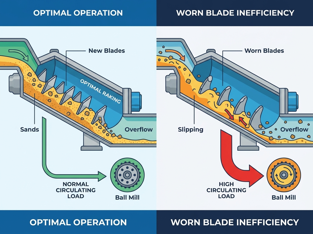
Inefficient raking directly forces the ball mill to process a poorly optimized circulating load. A healthy classification circuit separates fines from coarse material cleanly. When Spiral Classifier Wear Blades degrade, they fail to pull sufficient coarse material out of the pool. Fines get trapped in the heavy sand bed. They travel back to the mill needlessly. This artificial increase in circulating load throttles your fresh feed capacity. You effectively waste mill energy grinding particles already small enough for downstream processing. Plant throughput drops rapidly.
Worn or missing blade sections alter fundamental fluid dynamics. A stable settling pool remains crucial for accurate particle separation. When blade geometry becomes irregular, it creates violent, localized turbulence. This undesirable agitation stirs up the heavy sand bed. The disrupted fluid forces oversized particles upward into the overflow weir. Downstream flotation or leaching circuits then receive unacceptably coarse material. These oversized particles reduce chemical recovery rates and clog downstream pump systems.
Operating degraded classification equipment guarantees financial loss through energy waste. We can measure this inefficiency across several vectors. First, the mill consumes massive electrical power regrinding fines. Second, you pump excess water to manage turbulent overflow densities. Third, the classifier motor draws more amperage struggling against stalled sand beds. You must view these energy leaks as direct financial penalties. Replacing worn components eliminates these penalties. The cost of new parts often pales in comparison to the monthly power bill savings.
You must measure the gap between the blade edge and the classifier tank floor. We call this the radial clearance. A factory-new installation typically maintains a tight, uniform gap. This tight tolerance prevents coarse material from slipping backward down the incline. Over time, abrasion eats away the metal. The gap widens. Once this clearance exceeds the manufacturer's maximum acceptable threshold, classification efficiency drops unacceptably. Maintenance teams should use specialized calipers or clearance gauges during every shutdown. Never rely on visual guessing to evaluate this critical dimension.
Outer edges travel the fastest during operation. They cover more distance per revolution than the inner sections near the shaft. Consequently, they see the highest velocity of abrasive contact. You will notice edge rounding and tapering long before the central sections degrade. This uneven wear changes the component's attack angle. A tapered profile loses its ability to dig into the settled sand bed. The material slips around the edges instead of moving upward. Once rounding significantly alters the attack angle, you must schedule a replacement.
Operators frequently ignore mounting points during routine inspections. You must inspect these connections carefully. Abrasive slurry constantly washes over the bolting hardware. It scours the metal around the mounting holes. Over time, perfectly round holes elongate into ovals. The fasteners themselves suffer from metal fatigue. Wear here compromises structural integrity immensely. Even if the primary raking surface remains somewhat intact, a weakened mounting point risks catastrophic detachment. A loose component tearing through the tank causes far more downtime than a scheduled change-out.
Uneven wear indicates problematic flow channelization inside the tank. Sometimes, slurry currents concentrate along specific paths. This creates aggressive, localized scour patterns on a few specific sections. You might find three completely ruined sections next to perfectly healthy ones. This discovery prompts immediate localized replacements. You do not always need full-shaft overhauls. Swapping out the specific damaged sections restores balance quickly. However, you should also investigate why the flow channelized in the first place to prevent recurring damage.
Wear Indicator | Physical Cause | Operational Impact | Required Action |
|---|---|---|---|
Excessive Radial Clearance | Uniform abrasion along the outer edge | Coarse sand slips back into the pool | Measure gap; replace if over OEM limit |
Edge Tapering | High-velocity contact on outer radius | Loss of attack angle and digging power | Replace heavily tapered outer segments |
Elongated Bolt Holes | Slurry scouring around fasteners | High risk of catastrophic detachment | Immediate hardware and blade replacement |
Localized Gouging | Flow channelization or tramp metal | Turbulence in the settling zone | Spot-replace affected sections; check feed |
An inability to maintain stable overflow density strongly points to degraded spiral performance. Operators usually control density by adjusting fresh feed and dilution water. If you keep these inputs strictly consistent but still see wild density swings, your equipment is failing. The missing surface area prevents the spiral from pulling out a steady stream of sand. The pool volume surges and collapses unpredictably. These density fluctuations destroy downstream process stability. When your control room data shows unexplainable variance, you should immediately inspect the physical classification hardware.
Unevenly worn profiles cause severe main shaft imbalance. As sections wear down at different rates, the weight distribution across the spiral changes. The heavy, asymmetrical load forces the shaft to wobble during rotation. This wobble creates deep mechanical strain. It sends destructive vibrations down into the lower submerged bearing. Lower bearings are notoriously difficult and expensive to replace. Ignoring vibration usually results in bearing failure. You can avoid this massive repair bill by simply keeping the spiral dynamically balanced through timely replacements.
Operators call it "slipping" when coarse sand builds up and cascades backward. You can observe this phenomenon visually if you look down the incline. The equipment rotates, but the sand bed remains largely stationary. The worn profiles lack the necessary depth to grip and lift the heavy material. They simply slice through the top layer of sand. The heavy particles cascade back down the slope. This creates a massive, stagnant load at the bottom. Slipping is a definitive, undeniable signal. You must swap out the damaged components immediately.
You must audit the exact failure mode of your outgoing components before ordering new ones. Do not simply reorder the exact same specification blindly. Examine the discarded metal. Does it show deep, high-impact gouging? This indicates large, sharp rocks hitting the surface forcefully. Alternatively, does it show smooth, polished wear? This indicates fine-particle abrasion. Understanding your specific abrasive profile helps you select the correct upgraded materials. Upgrading your Mining Wear Parts correctly extends maintenance intervals significantly.
High-chrome white iron stands as the undisputed standard for heavy-duty applications. Foundries cast these alloys to withstand extreme abrasion. They offer exceptional hardness, making them perfect for highly siliceous ores. However, you must consider the trade-offs. High-chrome alloys are inherently brittle. They do not handle sudden, massive impact shocks well. Furthermore, they are incredibly heavy. This extra weight puts more continuous strain on your drive motor and gearbox. You should deploy high-chrome solutions when pure sliding abrasion is your primary enemy.
Synthetics offer brilliant solutions for specific environments. Polyurethane and rubber coatings excel in fine-grained, highly corrosive, or low-impact applications. They resist chemical attacks from flotation reagents perfectly. They also handle fine-particle abrasion remarkably well. One major benefit involves structural weight. Synthetics weigh significantly less than thick steel or iron alloys. This reduced weight lowers the continuous load on your drive train. It saves electrical energy and prolongs gearbox life. Consider synthetics if your process handles finer grinds or acidic slurries.
Replacing these components requires a meticulously planned maintenance outage. You cannot rush this process safely. First, you must completely drain the classifier tank. Next, crews must wash out the compacted sand bed manually. Most importantly, you must isolate all hazardous energy. Lockout/tagout (LOTO) procedures are strictly non-negotiable. The drive motor must be mechanically and electrically secured. Planning these steps in advance reduces actual wrench-time significantly. Proper planning ensures your maintenance crew works safely inside the confined tank space.
Expect to encounter heavily corroded fasteners. The submerged sections live in a highly abrasive, often corrosive environment. Bolts will seize. Nuts will round off. Do not waste hours trying to loosen heavily impacted hardware with standard hand tools. We recommend establishing aggressive cutting and heating protocols beforehand. Use oxy-acetylene torches or portable grinders to remove stubborn bolts quickly. Protect the main spiral shaft during cutting. Minimizing shaft damage remains your top priority while stripping away the old metal.
You must maintain the dynamic balance of the main shaft during reassembly. Never replace heavy metallic sections randomly. We advise replacing them in symmetrical sets. If you change a section on the left side, change the corresponding section on the right side. If you are doing a partial replacement, stagger the new, heavier parts correctly alongside the older, lighter parts. Poor balancing leads directly to the destructive vibrations discussed earlier. A balanced shaft spins smoothly and protects your expensive lower bearing.
Installation does not end when you tighten the last bolt. You must perform strict clearance calibrations. Manually rotate the massive shaft before turning on the power. Check the gap between every newly installed section and the tank bottom. New parts are taller and wider. They might foul against the tank floor during the initial start-up under load. Adjust the main shaft lifting device if necessary. Verifying this clearance prevents catastrophic structural damage the moment you hit the start button.
Relying on a reactive, run-to-failure strategy for classification equipment creates unacceptable bottlenecks. Your grinding circuit represents the heart of your mineral processing plant. When you let classifier efficiency degrade, you choke the entire system. Fines recirculate endlessly, energy gets wasted, and recovery rates plummet. You must treat these components as critical process variables, not just durable metal.
Replacement decisions must always be driven by strict clearance measurements and process data. Spikes in circulating load and erratic overflow densities tell a clear story. Never rely solely on subjective visual inspections from the tank walkway. Get inside, measure the radial gaps, and analyze your control room trends.
We strongly recommend scheduling a comprehensive wear audit immediately. Measure your current clearances during your next scheduled shutdown. Consult with an engineering team to match the correct replacement alloy or synthetic material to your specific operational profile. Proactive, data-driven replacement is the only way to maximize your plant's profitability.
A: Average lifespans vary wildly, ranging from 3 months to over 2 years. This depends heavily on ore abrasiveness (Silica Work Index), rotational speed, and material composition. You should let physical measurement, not time, dictate replacement schedules.
A: The lower, fully submerged blades typically wear much faster due to the heavy sand bed. Partial replacement is common and highly cost-effective. However, you must ensure the replacement pattern maintains the dynamic balance of the main shaft.
A: Hydrocyclone apex wear immediately ruins classification sharpness. In contrast, spiral classifier wear is slow and progressive. This gradual decline is dangerous because it often masks severe process inefficiency until massive bottlenecks occur.
A: Bolted designs are overwhelmingly preferred in modern operations. They allow for rapid, safe replacement in the field. They eliminate the specialized labor requirements and severe fire risks associated with underground or in-plant welding.
